
Balance Chain installation is used in the installation of high-speed lifts to minimise the unbalanced rope load that occurs on the drive pulley due to the different weights of the loads (suspension ropes, flex cables). Thus, the weight and motor are fixed on the drive pulley without taking the cabin area into account. Unless the unstable weight effect of the suspension ropes is balanced, it can cause insufficient or excessive traction force, which can lead to undesirable hazardous situations. In addition, the torque required on the lift motor is reduced by using a balancing rope or cable.
Balancing is generally required for travel distances exceeding 30 metres. At rated speeds exceeding 3.5 m/s, steel wire ropes are used to meet the requirements of ASME 17.1 and EN81-1 standards. These are attached to the bottom of the cabin, pass through the tensioning and guiding pulley at the bottom of the shaft, and are finally connected to the bottom of the counterweight frame.
At declared speeds exceeding 3.5 m/s, the tensioning pulley must be equipped with an anti-rebound device. When the anti-rebound device is activated, an electrical safety device must stop the lift machine. For speeds below 3.5 m/s, chain-type balancing systems may be used. These cables are cheaper than wire rope systems and simpler as the system does not require any tensioning device at the bottom of the shaft.
Balancing systems used in lift systems are employed to counterbalance the weight of the load ropes as the cabin moves up and down the shaft. Balancing cables include simple chains, plastic-coated chains, chains with braided webbing cables, and plastic aggregate mixtures to create round and flat configurations. This study defines the existing types of balancing cables that can be used in the installation of new and recently introduced products with a rated speed of less than 3.5 m/s.
 Balancing is generally required for travel distances exceeding 30 metres. At rated speeds exceeding 3.5 m/s, steel wire ropes are used to meet the requirements of ASME 17.1 and EN81-1 standards. These are attached to the bottom of the cabin, pass through the tensioning and guiding pulley at the bottom of the shaft, and are finally connected to the bottom of the counterweight frame.
At declared speeds exceeding 3.5 m/s, the tensioning pulley must be equipped with an anti-rebound device. When the anti-rebound device is activated, an electrical safety device must stop the lift machine. For speeds below 3.5 m/s, chain-type balancing systems may be used. These cables are cheaper than wire rope systems and simpler as the system does not require any tensioning device at the bottom of the shaft.
Balancing systems used in lift systems are employed to counterbalance the weight of the load ropes as the cabin moves up and down the shaft. Balancing cables include simple chains, plastic-coated chains, chains with braided webbing cables, and plastic aggregate mixtures to create round and flat configurations. This study defines the existing types of balancing cables that can be used in the installation of new and recently introduced products with a rated speed of less than 3.5 m/s.
All these components must be installed in the lift shaft as required. As a general rule, the lift car is suspended from the counterweight by a suspension rope wound around one or more pulleys located at the top of the lift shaft. One end of the counterweight rope is connected to the counterweight and the other end is wound around a counterweight cable pulley located at the bottom of the lift shaft in some cases. In other cases, the counterweight cable (chain) may be left hanging in the shaft without being wound around the pulley.
The counterweight is actually the same weight as the cabin loaded with half the load, and the weight of the suspension ropes is actually equal to the weight of the balancing cable (chain). One end of the flex cable is attached to the bottom of the cabin and the other end is attached to a connection box fixed to the side wall of the lift. Signals are sent via the flex cable to the driver unit (control panel), which implements the commands sent from the cabin.
The primary function of the balancing cable is to maintain the dynamic balance of the suspension rope weight as the cabin moves up and down within the lift shaft. This ensures that the cabin is always dynamically balanced. If the balancing cable is omitted from the system, the weight of the suspension ropes shifts from one side of the drive pulley to the other, causing the weight to fluctuate as the cabin moves up and down the lift shaft. For example, when the cabin is at the bottom and the counterweight is at the top, the force required to move the cabin will be equal to the total weight of the people inside and the suspension ropes.
As the cabin rises, the weight of the suspension ropes is transferred by the cabin over the drive pulley to the counterweight side. For optimum performance, the total weight of the suspension ropes will essentially equal the weight of the counterweight cable at any position of the cabin within the lift shaft. Additionally, the length of the suspension ropes between the cabin and the drive pulley (Suspension type; 1:1) will be equal to the length of the compensating rope between the cabin and the lowest part of the counterweight cable. For safety reasons, there may be five or more suspension ropes, and the total weight of these ropes will be approximately equal to the weight of the counterweight rope.
Almost all lift systems do not use lower pulleys; systems installed where the counterweight chains are freely suspended are subject to wind or other forces generated by the moving lift. In previous bare chain-type counterweight chains, they form a point where two links join at the turning point at the bottom of the shaft. This situation arises from the highly flexible nature of the chain and the limited dimensions of the lift shaft. At this point, as the cabin moves up and down, one link strikes the other, causing unwanted noise, wear and the risk of the chain striking the cabin.
The links of a structure completely filled with plastic remain perfectly straight due to the filler material, which is the exact opposite of the situation encountered in previously used balancing systems that caused the length of the connecting chain to decrease. A completely flat chain link bundle causes the weight of the chain to be distributed evenly, prevents noise and one link from wearing down another, protects the cylindrical surface of the roller, and prevents roller cracking.
 When manufactured in a cylindrical structure, this type of round filled balance chain has the following characteristics:
* Soft, wear-resistant outer surface (PVC)
* Contains a chain, steel cable or similar material in the centre.
* The iron material (chain) inside is firmly held in place by the plastic filling material beneath the cylindrical outer surface.
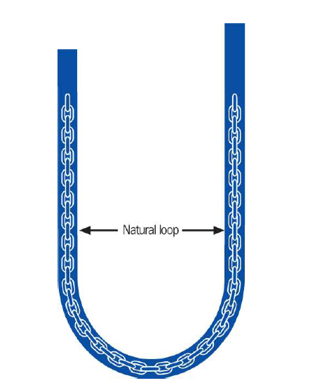
Recent developments in balance chains have primarily focused on replacing the bare chain with something else. The aim is to operate with less noise and lower costs. Most balance chains are different versions of coated chains and have approximately the same flexibility as chains. Since balance chains generally replace bare chains, there is a need to create the same tight turning radius as in chains in order to connect to the same support points under the cabin and counterweight. Balance chains form an S shape when suspended from their connection points. The width of this S turn depends on the flexibility of the cable. Like the bare chain they replace, traditional balance chains also form a very tight turn, and the balance chain is attached close to the edge of the cabin due to this tight S turn.
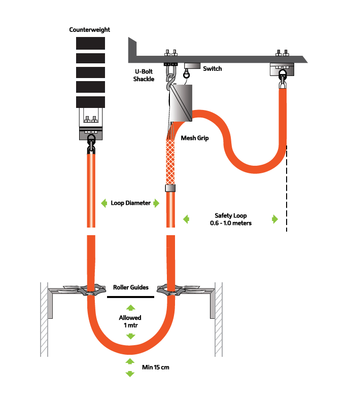
Establishing a pre-calculated and predetermined natural swing measurement is crucial for the safe operation of the lift. A swing measurement that is wider than required can cause the cable to swing much more than necessary at the bottom of the shaft. This can be dangerous and damaging; excessive chain swaying can cause the chain to potentially catch on buffers, buffer switches, consoles, and other equipment at the bottom of the shaft. In the event of any cable entanglement, there is a risk to public safety, and there is also a high probability of damage to equipment at the bottom of the shaft and/or in the lift shaft. Therefore, the connection point of the balance chain should be the point where the cable’s natural swing radius meets it.
Establishing a pre-calculated and predetermined natural swing measurement is crucial for the safe operation of the lift. A swing measurement that is wider than required can cause the cable to swing much more than necessary at the bottom of the shaft. This can be dangerous and damaging; excessive chain swaying can cause the chain to potentially catch on buffers, buffer switches, consoles, and other equipment at the bottom of the shaft. In the event of any cable entanglement, there is a risk to public safety, as well as a high probability of damage to equipment at the bottom of the shaft and/or in the lift shaft. Therefore, the connection point of the balance chain should be the point where the cable’s natural swing radius meets it.
Lift manufacturers have determined that when the chain’s connection point is close to the edge of the cabin, the resulting excessive shearing load limits the bare chain to a maximum suspension height of approximately 122 metres. (NOTE: The maximum sag length of a modern balance chain depends on the strength of the connection element).
The problem lies more in the weight than the length. A stabiliser of 122 metres or longer can upset the cabin’s balance, and side-to-side weight configurations can also reduce performance.
Nowadays, a number of methods are used to balance long compensation lengths. Some companies mount static weights hanging from the cabin opposite the compensation connection point. This only provides a certain degree of counterweight and reduces the cabin’s overall performance by weighing down its potential capacity.
Another method is to install an additional balance chain, such as a flex cable, directly opposite the main balance chain connection point. This dynamically balances the existing main balance chain and is a more suitable solution for static loads. However, this method increases the cost of the cable, the connection hardware and the installation time, while reducing the capacity of the cabinet due to the extra load. A more practical solution is to use a balance chain with a wider natural rotation angle that allows connection to the centre of the cabinet.
Another method is to install an additional balance chain, such as a flex cable, directly opposite the main balance chain connection point. This dynamically balances the existing main balance chain and is a more suitable solution for static loads. However, this method increases the cost of the cable, the connection hardware and the installation time, while reducing the capacity of the cabinet due to the extra load. A more practical solution is to use a balance chain with a wider natural rotation angle that allows connection to the centre of the cabinet.
Flex cable has been used as a balancing element for many years. It accommodates a wider range of rotation and typically requires only a single device for its fixed and specific movement path during operation. However, this is not an ideal solution. The cost of the flexible cable is roughly four times that of the compensation cable it replaces. Flexible cable must be securely connected at both ends to prevent bending and breakage caused by the premature failure of the single-core cables inside. When used as a balancing chain, the cable must be shortened periodically as the suspension ropes stretch over time.
A more practical solution is to use a balance chain with a wider natural rotation angle that allows attachment to the centre of the cabin. Flexible cable has been used as a balancing element for many years. It meets the need for a wider rotation angle, and the fixed and specific movement path during operation usually requires only a single device. However, this is not an ideal solution. The cost of the flexible cable is roughly four times that of the compensation cable it replaces. Flex. Cable must be securely connected at both ends to prevent bending and breakage caused by the premature failure of the single-core cables inside. When Flex. Cable is used as a balance chain, the cable must be shortened periodically as the suspension ropes stretch over time.
The wide turning radius balance chain is commercially available today with a turning radius of approximately 1.2 metres. This swing radius allows the chain to be suspended from the centre of the cabin, ensuring advanced balance and ride quality. This provides an excellent solution for lifts with a suspension length of 122 metres that have lateral balance weights or balance issues.
Elevator designs requiring flex cables for balancing currently offer a solution that matches low vibration performance and is also cost-effective in terms of installation and refurbishment costs.
Aufzugskonstruktionen, die zur Gewichtsausgleichung flexible Kabel erfordern, bieten derzeit eine Lösung, die eine geringe Vibrationsleistung aufweist und zudem hinsichtlich der Installations- und Modernisierungskosten kostengünstig ist.
As Güven Çelik Halat Ltd. Co., we offer our customers quality with the G-Flex Lift Balance Chain.
The counterweight chain is generally secured at one end under the cabin and at the other end to the bottom of the shaft, passing through a guide pulley and terminating under the counterweight frame. When securing the chain within the system, it must be ensured that it operates in accordance with the natural rotation diameter. If the rotation diameter is larger than the natural rotation diameter, the counterweight chain will swing during lift operation.
This situation may also cause the chain to become entangled with other components within the shaft, causing damage and compromising the overall operation of the system. Therefore, the connection point of the balance chain should be at the point where the chain’s natural turning radius accommodates it. This is extremely important for the safe operation of the lift. When the counterweight chain is mounted according to its natural turning radius, it may sometimes be fixed close to the edge of the cabin. In such an installation, the weight of the counterweight chain may cause the cabin to become unbalanced. This balance must be achieved either by placing a fixed weight under the cabin or by using other methods.